Technical Drawings
Battery Charging Circuit
This circuit charges a battery using the AD2’s programmable power supply (PPS).
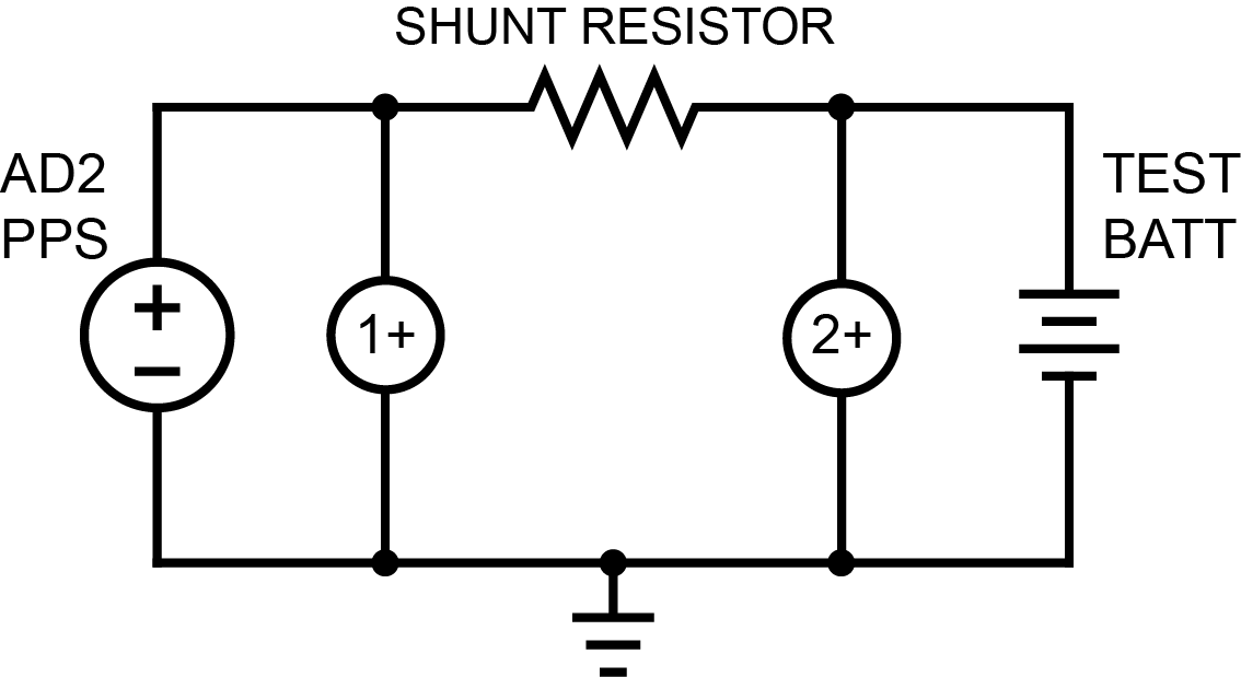
The charge current is read with the two voltmeter channels of the AD2, 1+ and 2+. This allows us to get a differential voltage measurement across a known resistance, and therefore calculate the current simply:
Programmatic Operation
In order to use this test circuit as a constant current source, one must run a loop that adjusts the PPS output constantly to the desired current. This current is calculated using the above formula, for which a precise value of \(R_{shunt}\) must be known.
Limitations
When not running, the battery discharges into the AD2
Max current supply limited by \(R_{shunt}\) value and AD2’s max PPS voltage of 5V
Current measurement accuracy limited by \(R_{shunt}\) value and AD2’s voltage measurement accuracy
Battery Discharging Circuit
This circuit is a simple electronic load. It works by connecting resistors in parallel to achieve lower and lower resistances. These resistors are selected by relays, an electromechanical switch.
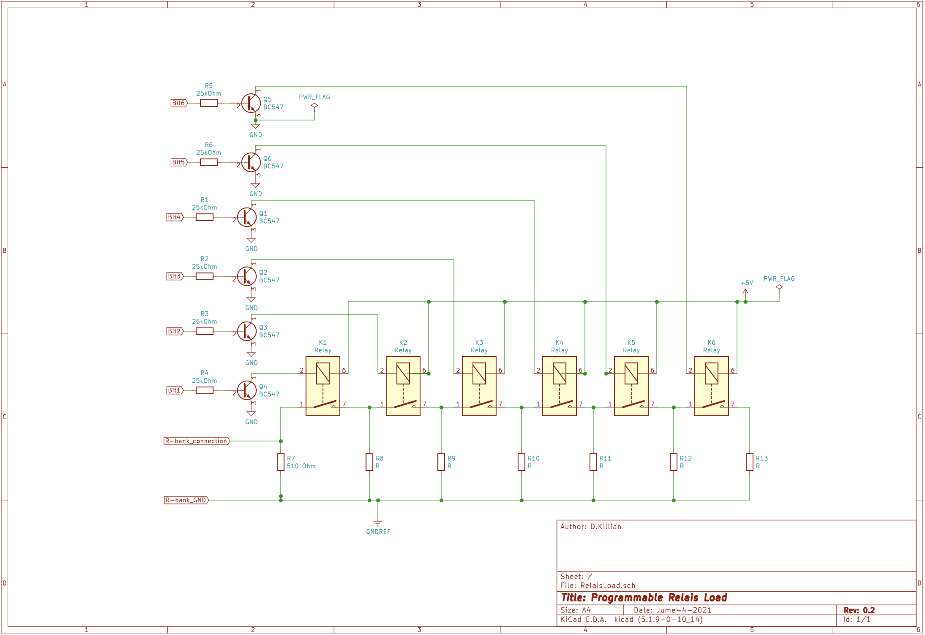
With six “bits” the load can be varied between ~500 Ω and ~10 Ω. Every extra “bit” divides the load by roughly 2.
Bits ON |
Load Value (Ω) |
|---|---|
None |
510 |
1 |
225 |
1 and 2 |
131 |
1, 2, and 3 |
65.9 |
1, 2, 3, and 4 |
32.9 |
1, 2, 3, 4, and 5 |
16.9 |
1, 2, 3, 4, 5, and 6 |
8.9 |
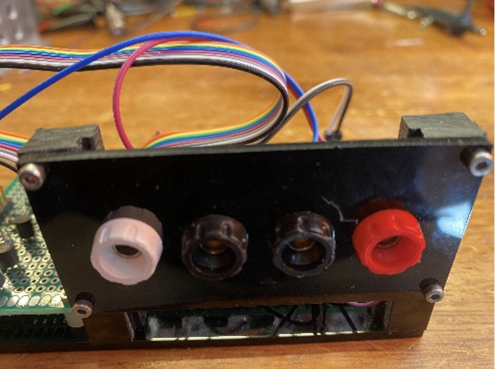
This little panel contains 4 banana sockets. From left to right:
White: the connection to the load.
Black 1: common connection for the load
Black 2: GND for the 5 Volts supply
Red: connection for +5 Volts
The load connections are totally separated from everything else.
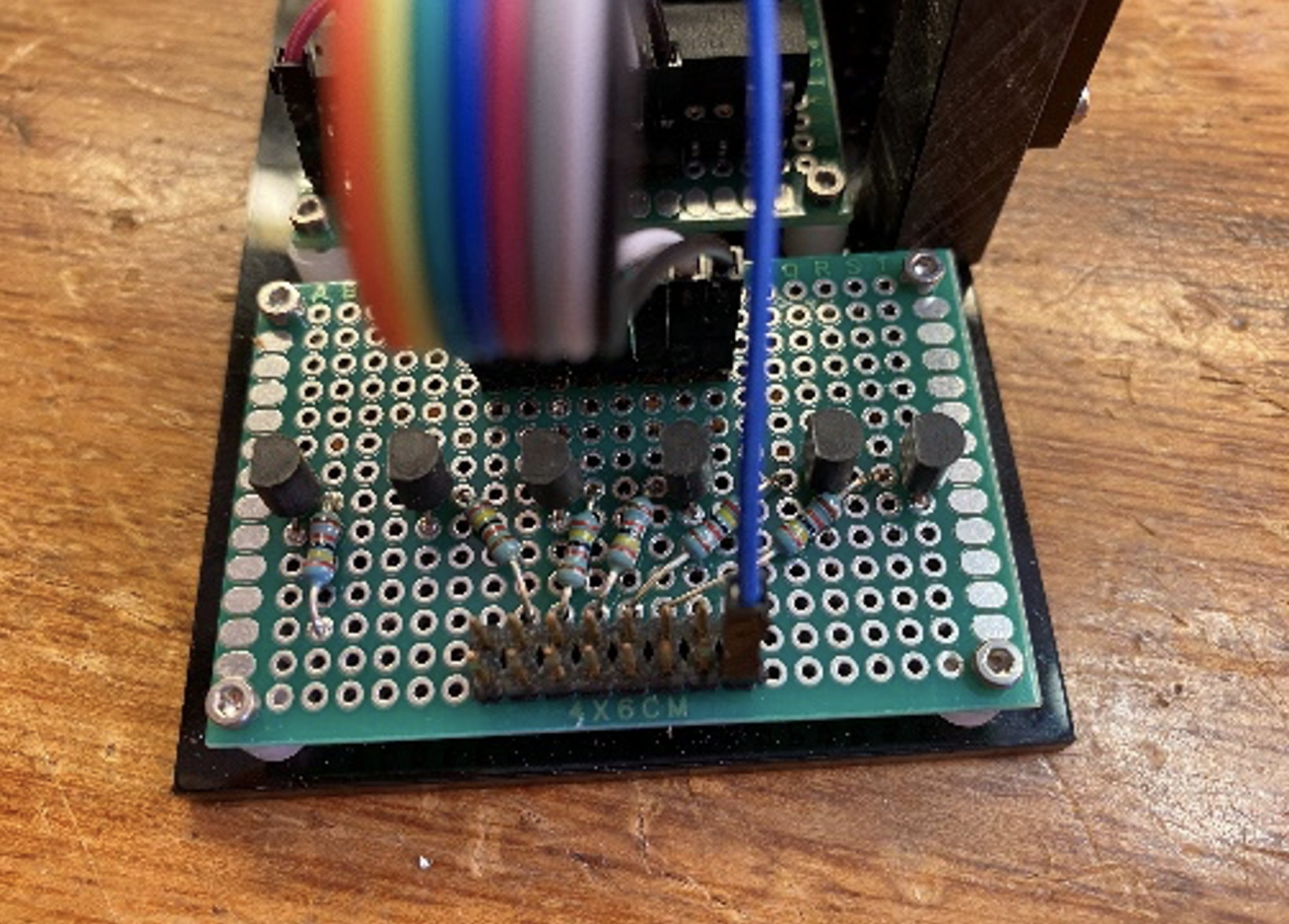
Use the double row header to connect the digital signals from the AD2 to switch the load. Beware, the bottom row is all GND. The top row starts from left to right with bit 1 to 6. 7 and 8 (the two most right ones) are not connected, but can be used in the future.
Programmatic Operation
In order to use this circuit as a CR sink, simply connect the control bits according to table: Control Bits and Resulting Resistance. If instead a CC sink is desired, one could measure voltage drop over the load, and knowing the current set resistance, calculate the discharge current from the battery.
Limitations
Limited number of discrete steps greatly limits smooth CC functionality.
Max power dissipation limited by 1/4 W resistors -> Parallelled allows more, but resistances are not the same, so current is not dissipated equally